Situation Analysis
Public Configurations
Context
Context
Currently, the intelligent analysis service can be implemented only on cameras.
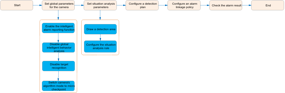
Cameras perform intelligent analysis using its own algorithm, and report alarms and snapshots to the HWT-IVS1800. The HWT-IVS1800 stores and manages alarms and displays alarms on the client. Figure 4-227 shows the process.

Configuration Process
Set related parameters on the LDU for situation analysis. Figure 4-228 shows the configuration process.
Function Description
Table 4-209 describes the camera intelligence requirements.
Application Limitations
- For details about the data retention period and clearance rules, see Data Clearance Rules.
- To configure intelligent analysis for cameras on the iClient S100, the camera version must be 9.0.0 or later.
Setting Global Parameters (Based on Cameras)
Context
- The intelligent attribute of the camera is automatically set to Others when an intelligent analysis function is enabled.
- Cameras have been configured to synchronize time with the HWT-IVS1800. This function is enabled by default. For details, see Configuring Time Synchronization from a Camera to the HWT-IVS1800.
Procedure
- Log in to the LDU as the admin user. (
 Logging In to the LDU)
 - Disable global intelligent behavior analysis and target recognition.
- For details about how to disable global behavior analysis for a camera, see 4.
- For details about how to disable target recognition for a camera, see Enabling Target Recognition.
- Set the camera algorithm mode. You need to set the camera algorithm mode only for some camera models. If the camera algorithm mode is not displayed, skip this step.
- Click
 in the upper left corner.
 - Choose Intelligent Application > Camera Intelligence > Algorithm Mode.
- Set the camera algorithm mode, as shown in Figure 4-229.
Table 4-210 Parameter description
Parameter
Setting
Algorithm Mode
Select Behavior Analysis.
- Click

Related Feature Operations
For details about operations related to situation analysis, see the feature guide.
Queue Length Detection
Feature Description
Definition
Intelligent cameras detect the queue length in a specified area and generate an alarm when the queue length exceeds the specified threshold.
The system receives and processes queuing information and alarms reported by intelligent cameras.
Customer Benefits
- The system automatically detects key information in video, reducing labor costs and improving work efficiency.
- The system supports around-the-clock detection or detection for a specified duration, eliminating issues that may occur due to security personnel's mistakes.
- Users only need to view live video upon an alarm. This allows a user to centrally manage a large number of cameras, reducing labor costs.
Application Scenario
This feature applies to places where people may need to wait in queues, for example, in bank branches.
Requirements
NE |
Version Requirement |
License Requirement |
Function |
|---|---|---|---|
HWT-IVS1800-D/HWT-IVS1800-E |
11.1.0 and later versions |
N/A |
Receives head and shoulder information reported by cameras and processes alarms. |
iClient S100 |
V1.6.0 and later versions |
N/A |
Receives and displays head, shoulder, and alarm information from cameras. |
SDC |
Intelligent analysis results superimposed on live video: 9.0.0 and later versions Information reporting through northbound interfaces: 9.0.0 and later versions |
N/A |
Supports crowd flow analysis. |
Application Limitations
Related configurations need to be performed in the camera web system.
Feature Configuration (Based on Cameras)
Scenario Description
Table 4-211 describes the support for this feature in different client scenarios.
Client |
Feature Support |
Reference |
|---|---|---|
LDU |
Supported |
For details, see Procedure (on the LDU). |
Camera web system |
Supported |
Complete the configuration by referring to the product documentation of cameras. |
iClient S100 |
V1.6.0 and later versions |
For details, see Procedure (on the iClient S100). |
Prerequisites
- You have set the parameters listed in Public Configurations.
- You have configured alarm linkage on the iClient S100. For details, see Configuring Alarm Linkage.
Procedure (on the LDU)
To view the configuration guide video, you can click  in the upper left corner on the Configuration tab page, and scan the QR code.
- Log in to the LDU as the admin user. ( Logging In to the LDU)
- Click
 in the upper left corner.
 - Choose Intelligent Application > Camera Intelligence > Situation Analysis > Queue Length.
- Configure queue length detection, as shown in Figure 4-230.
Table 4-212 describes the key parameters.
Table 4-212 Parameter descriptionType
Parameter
Description
-
Detection switch
Button for enabling or disabling queue length detection.
After the switch is toggled on, the system enables the queue length detection function.
Detection area
No.
ID of a detection area. Only one detection area can be drawn.
Operation
Column containing the icons for drawing or deleting a detection area on the video image.
To draw a detection area, select polygon vertices on the video image and right-click the image. The system automatically connects the selected vertices to form a closed area.
If no detection area is drawn, the full image is used as the detection area by default.
Configuration
Detection Sensitivity
Detection sensitivity.
The default value is standard.
Single Processing Time (s)
Queuing duration of a single person.
Alarm Threshold (min)
Alarm threshold.
Alarm Interval (s)
Interval at which alarms are checked, in seconds.
Scheduled Data Reporting
Indicates whether to report data periodically. If this check box is selected, you can set Data Report Interval (s). The device reports the current queuing duration and number of queuing persons to the platform at a specified interval.
Sound And Light Alarm
Audio switch/Twinkle switch
Indicates whether to produce audible alarms (playing audio files) or visual alarms (blinking light) when an alarm is triggered.
Audio Output
Audio file to be played when an alarm is triggered.
- You can directly use this function when an intelligent IR/white-light camera with intercom is used.
- To use this function when a camera other than the intelligent IR/white-light camera with intercom is used, you need to set audio parameters for the camera and connect the camera to an external audio output device.
Frequency
Number of times for playing an audio file when an alarm is triggered.
Twinkle Freq
Frequency at which the light blinks when an alarm is triggered. You can set this parameter to Low frequency, Medium frequency, or High frequency as required.
Currently, the visual alarm (blinking light) function is available only for intelligent IR/white-light cameras with intercom. You need to set light-related parameters.
Twinkle Time(s)
Period in which the light blinks when an alarm is triggered.
- Configure an alert plan, as shown in Figure 4-231.
- Configure an alarm linkage policy, as shown in Figure 4-232.
Table 4-213 describes the key parameters and buttons.
Table 4-213 Parameter/Button descriptionType
Parameter
Description
Common Linkage
Display ID
Indicates whether to display the status icon of the camera that triggers an alarm on the live video viewing page. This function is used to notify users of an alarm generated by the current camera.
Full-Screen Alarm
Indicates whether to display alarms in full screen mode.
After this function is enabled, if a camera triggers an alarm and the live video viewing page is displayed on the LDU, the live video of the camera is played in full screen mode for 5s.
CAUTION:If other alarms are generated when the live video is played in full-screen mode, the full-screen alarm function is not triggered.
Send Email
- Indicates whether to send email notifications. After this function is enabled, the system sends an email to the configured email recipient when a service alarm is generated.
- You can click
 to customize the alarm email recipient and email body.
The email address for sending service alarms needs to be customized on the OMU portal.
For details about how to set the email address for sending service alarms, see How Do I Configure Connection to the SMTP Server?.
Recording
Channel
Camera to be linked to record video when an alarm is triggered.
Duration(s)
Customized recording duration. The value ranges from 5 to 3600, in seconds. You are advised to set this parameter to a value greater than or equal to 60 (default).
Triggered Snapshot
Channel
Camera to be linked to take snapshots when an alarm is triggered.
NOTE:If both snapshot taking and email sending are configured for alarm linkage, you can obtain both the alarm-triggered snapshots and the snapshots sent in the email.
Stop Recording
Channel
Camera to be linked to stop video recording when an alarm is triggered.
I/O Alarm
Channel ID
Alarm reporting channel.
Duration(s)
Customized alarm linkage duration.
The value ranges from 1 to 3600, in seconds.
NOTE:If the specified alarm linkage duration is different from the I/O alarm output duration configured in How Do I Connect Cables and Configure Alarm Input and Output Ports?, the shorter alarm duration is used.
For example, if the I/O alarm output duration is set to 20s and the alarm linkage duration is set to 30s, the actual alarm output duration is 20s.
Invoke Preset Position
Channel
Camera to be linked. When a service alarm is generated, the linked camera rotates to the specified preset position.
Before enabling preset position linkage, ensure that a preset position has been configured for the camera to be linked. For details about how to configure a preset position, see Feature Configuration.
Device
Name of the camera that is linked to a preset position.
Position
Preset position linked to the camera.


Procedure (on the iClient S100)
- On the iClient S100 home page, choose Maintenance Management > Smart Configuration.
- Click a camera under a device.
- Optional: For cameras in multi-algorithm mode, choose and set Algorithm mode to Behavior analysis.

After the algorithm mode is switched, the camera will restart for the setting to take effect. Wait for 3 minutes and then set intelligent services.
- Choose .
- Enable queue length detection and set parameters such as detection area parameters, as shown in Figure 4-233.
- Set parameters in the Parameter Settings area. Table 4-214 describes the parameters.
Table 4-214 Parameter description
Parameter
Description
Enable Queue Detection
Indicates whether to enable the current intelligent analysis task.
Alarm Detection Interval(s)
Interval at which alarms are checked, in seconds.
Single processing time(s)
Queuing duration of a single person.
Alarm threshold(min)
Alarm threshold.
Sensitivity
Detection sensitivity.
The value ranges from 1 to 5. A larger value indicates higher sensitivity.
- Set audible and visual alarm parameters. Table 4-215 describes the parameters.
Table 4-215 Audible and visual alarm parameters
Parameter
Description
Requirement on the Camera
Enable audio alarms
Indicates whether to produce audible alarms (play audio files) when an alarm is triggered.
- You can directly use this function when an intelligent IR/white-light camera with intercom is used.
- To use this function when a camera other than the intelligent IR/white-light camera with intercom is used, you need to set audio parameters for the camera and connect the camera to an external audio output device.
Audio file
Audio file to be played when an alarm is triggered.
To import an audio file to the iClient S100, choose Maintenance Management > Video Device > Device List on the home page, double-click the required camera that is connected to a device, and add an audio file on the Audio Channel tab page.
Playback times
Number of times for playing an audio file when an alarm is triggered.
Enable light flashing alarm
Indicates whether to produce visual alarms (blinking lights) when an alarm is triggered.
Currently, these functions are available when an intelligent IR/white-light camera with intercom is used. You need to set light-related parameters.
White light illuminator
Frequency at which the light blinks when an alarm is triggered. You can set this parameter to Low, Middle, High, or Steady on as required.
Flash duration (s)
Period in which the light blinks when an alarm is triggered.
- Set area parameters. Table 4-216 describes the buttons.
- Set plan parameters. Table 4-217 describes the parameters.
When the iClient S100 and an HWT-IVS1800 are in different time zones, the time set in the Plan Settings area refers to the time of the HWT-IVS1800.
Table 4-217 Plan settingsParameter/Button
Description
Add
Button for adding an alert plan. A maximum of eight alert plans are supported.
All Delete
Button for deleting all alert plans.
Start Time/End Time
Time segment during which alert is to be deployed.
Date
Date on which an alert plan is to be executed.
- Every day
- Monday to Sunday
Mode
Indicates whether to cyclically execute an alert plan.
- Weekly
- One-off
Operation
To delete the current alert plan, click
 in the Operation column.
- Set parameters in the Parameter Settings area. Table 4-214 describes the parameters.
- Click Save.

Feature Verification
You can view queue length information on the LDU using either of the following methods:
- View real-time queue length details on the live video viewing page.
- View queue length alarms in the alarm center.
Verification (Based on the LDU)
- Log in to the LDU as the admin user. ( Logging In to the LDU)
- View alarms on the LDU.
- Viewing real-time alarms
- Right-click on the desktop and choose Live > Alarm List.
- Click
 and select the type of alarms to be viewed, as shown in Figure 4-234.
- Click an alarm card in the alarm list to view the alarm in full screen mode, as shown in Figure 4-235.
- By default, the alarm-triggered video is 10s long (5s before and 5s after the alarm time).
- If you click
 , the alarm list on the left stops refreshing the latest alarms. If you click
  again, the system refreshes all new alarms generated after the alarm refresh stops.
- Viewing historical alarms
- Right-click on the desktop and choose Retrieval.
- Choose Event Retrieval.
- View alarms, as shown in Figure 4-236.
You can click the Browsing Status icon to switch the alarm browsing mode. Alarms in the alarm center can be browsed in card or list mode.
- Viewing real-time alarms


Verification (Based on the iClient S100)
- Viewing real-time service details
- On the iClient S100 home page, choose .
- Double-click an online camera in the Devices area or drag the online camera to a live video pane. Then you can view live video from this camera.
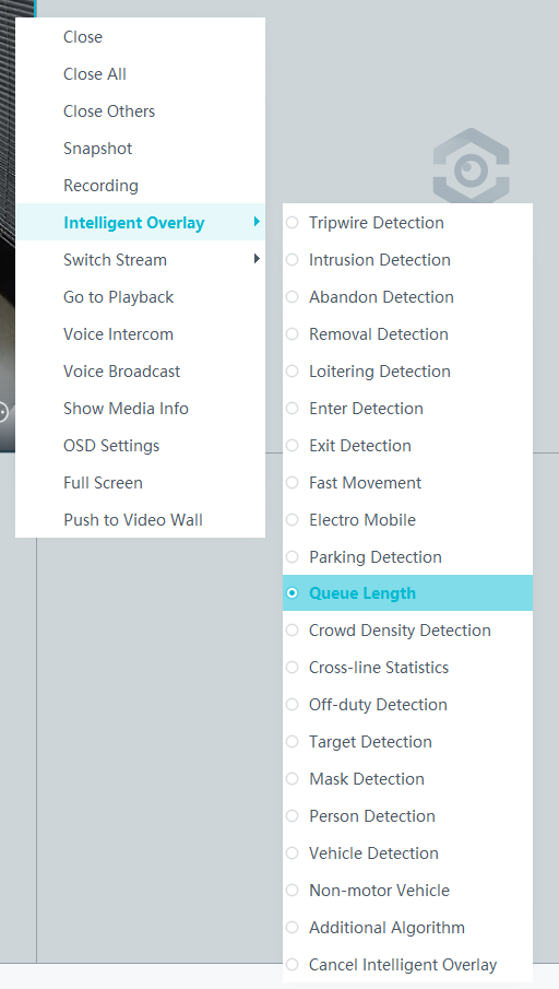
- Right-click a live video pane and choose Intelligent Overlay > Queue Length. The real-time intelligent analysis result is superimposed on the video image.Figure 4-237 Options under Intelligent Overlay
- Viewing alarms
For details about how to view the latest or historical alarms, see Viewing Alarms (on the iClient S100).
- Viewing alarms
Crowd Density Detection
Feature Description
Definition
- Cameras check whether the people flow exceeds the threshold in a specified area and reports an alarm if so.
- The system receives and processes crowd density information and alarms reported by intelligent cameras. Then security measures will be taken.
Customer Benefits
- The system automatically detects key information in video, reducing labor costs and improving work efficiency.
- The system supports around-the-clock detection or detection for a specified duration, eliminating issues that may occur due to security personnel's mistakes.
- Users only need to view live video upon an alarm. This allows a user to centrally manage a large number of cameras, reducing labor costs.
Application Scenario
This feature applies to places that have strict restrictions on crowd density, for example, tourist attractions and campuses.
Requirements
NE |
Version Requirement |
License Requirement |
Function |
|---|---|---|---|
HWT-IVS1800-D/HWT-IVS1800-E |
11.1.0 and later versions |
N/A |
Receives head and shoulder information reported by cameras and processes alarms. |
iClient S100 |
V1.6.0 and later versions |
N/A |
Receives and displays head, shoulder, and alarm information from cameras. |
SDC |
Intelligent analysis results superimposed on live video: 9.0.0 and later versions Information reporting through northbound interfaces: 9.0.0 and later versions |
N/A |
Supports crowd flow analysis. |
Application Limitations
Related configurations need to be performed in the camera web system.
Feature Configuration (Based on Cameras)
Scenario Description
Table 4-218 describes the support for this feature in different client scenarios.
Client |
Feature Support |
Reference |
|---|---|---|
LDU |
Supported |
For details, see Procedure (on the LDU). |
Camera web system |
Supported |
Complete the configuration by referring to the product documentation of cameras. |
iClient S100 |
V1.6.0 and later versions |
For details, see Procedure (on the iClient S100). |
Prerequisites
You have set the parameters listed in Public Configurations.
Procedure (on the LDU)
To view the configuration guide video, you can click in the upper left corner on the Configuration tab page, and scan the QR code.
- Log in to the LDU as the admin user. ( Logging In to the LDU)
- Click
 in the upper left corner.
 - Choose Intelligent Application > Camera Intelligence > Situation Analysis > Crowd Density Detection.
- Configure crowd density detection, as shown in Figure 4-238.
Table 4-219 describes the key parameters.
Table 4-219 Parameter descriptionType
Parameter
Description
-
Detection switch
Button for enabling or disabling crowd density detection.
After the switch is toggled on, the system enables the crowd density detection function.
Detection Area
No.
ID of a detection area. Only one detection area can be drawn.
Operation
Column containing the icons for drawing or deleting a detection area on the video image.
To draw a detection area, select polygon vertices on the video image and right-click the image. The system automatically connects the selected vertices to form a closed area.
If no detection area is drawn, the full image is used as the detection area by default.
Configuration
Scheduled data reporting
Indicates whether to report data periodically. If this check box is selected, you can set Data Report Interval (s). The camera reports the current crowd density and number of persons to the platform at a specified interval.
Detection Sensitivity
Customized detection sensitivity.
Higher sensitivity indicates a higher probability of triggering alarms and a higher false positive rate.
Alarm Threshold
Alarm threshold for the number of people in an area. An alarm is generated when the total number of people in the area exceeds the alarm threshold.
Sound And Light Alarm
Audio switch/Twinkle switch
Indicates whether to produce audible alarms (playing audio files) or visual alarms (blinking light) when an alarm is triggered.
Audio Output
Audio file to be played when an alarm is triggered.
- You can directly use this function when an intelligent IR/white-light camera with intercom is used.
- To use this function when a camera other than the intelligent IR/white-light camera with intercom is used, you need to set audio parameters for the camera and connect the camera to an external audio output device.
Frequency
Number of times for playing an audio file when an alarm is triggered.
Twinkle Freq
Frequency at which the light blinks when an alarm is triggered. You can set this parameter to Low frequency, Medium frequency, or High frequency as required.
Currently, the visual alarm (blinking light) function is available only for intelligent IR/white-light cameras with intercom. You need to set light-related parameters.
Twinkle Time(s)
Period in which the light blinks when an alarm is triggered.
- Configure an alert plan, as shown in Figure 4-239.
- Configure an alarm linkage policy, as shown in Figure 4-240.
Table 4-220 describes the key parameters and buttons.
Table 4-220 Parameter/Button descriptionType
Parameter
Description
Common Linkage
Display ID
Indicates whether to display the status icon of the camera that triggers an alarm on the live video viewing page. This function is used to notify users of an alarm generated by the current camera.
Full-Screen Alarm
Indicates whether to display alarms in full screen mode.
After this function is enabled, if a camera triggers an alarm and the live video viewing page is displayed on the LDU, the live video of the camera is played in full screen mode for 5s.
CAUTION:If other alarms are generated when the live video is played in full-screen mode, the full-screen alarm function is not triggered.
Send Email
- Indicates whether to send email notifications. After this function is enabled, the system sends an email to the configured email recipient when a service alarm is generated.
- You can click to customize the alarm email recipient and email body.
The email address for sending service alarms needs to be customized on the OMU portal.
For details about how to set the email address for sending service alarms, see How Do I Configure Connection to the SMTP Server?.
Recording
Channel
Camera to be linked to record video when an alarm is triggered.
Duration(s)
Customized recording duration. The value ranges from 5 to 3600, in seconds. You are advised to set this parameter to a value greater than or equal to 60 (default).
Triggered Snapshot
Channel
Camera to be linked to take snapshots when an alarm is triggered.
NOTE:If both snapshot taking and email sending are configured for alarm linkage, you can obtain both the alarm-triggered snapshots and the snapshots sent in the email.
Stop Recording
Channel
Camera to be linked to stop video recording when an alarm is triggered.
I/O Alarm
Channel ID
Alarm reporting channel.
Duration(s)
Customized alarm linkage duration.
The value ranges from 1 to 3600, in seconds.
NOTE:If the specified alarm linkage duration is different from the I/O alarm output duration configured in How Do I Connect Cables and Configure Alarm Input and Output Ports?, the shorter alarm duration is used.
For example, if the I/O alarm output duration is set to 20s and the alarm linkage duration is set to 30s, the actual alarm output duration is 20s.
Invoke Preset Position
Channel
Camera to be linked. When a service alarm is generated, the linked camera rotates to the specified preset position.
Before enabling preset position linkage, ensure that a preset position has been configured for the camera to be linked. For details about how to configure a preset position, see Feature Configuration.
Device
Name of the camera that is linked to a preset position.
Position
Preset position linked to the camera.

Procedure (on the iClient S100)
- On the iClient S100 home page, choose Maintenance Management > Smart Configuration.
- Click a camera connected to a device and choose .
- Enable crowd density detection and set parameters such as detection area parameters, as shown in Figure 4-241.
- Set parameters in the Parameter Settings area. Table 4-221 describes the parameters.
Table 4-221 Parameter description
Parameter
Description
Alarm Check Interval (s)
Interval at which alarms are checked, in seconds.
Alarm threshold (Num)
Minimum number of persons in a detection area. If the actual number of persons reaches the value of this parameter, an alarm is reported.
Sensitivity
Detection sensitivity.
The value ranges from 1 to 5. A larger value indicates higher sensitivity.
- Set audible and visual alarm parameters. Table 4-222 describes the parameters.
Table 4-222 Audible and visual alarm parameters
Parameter
Description
Requirement on the Camera
Enable audio alarms
Indicates whether to produce audible alarms (play audio files) when an alarm is triggered.
- You can directly use this function when an intelligent IR/white-light camera with intercom is used.
- To use this function when a camera other than the intelligent IR/white-light camera with intercom is used, you need to set audio parameters for the camera and connect the camera to an external audio output device.
Audio file
Audio file to be played when an alarm is triggered.
To import an audio file to the iClient S100, choose Maintenance Management > Video Device > Device List on the home page, double-click the required camera that is connected to a device, and add an audio file on the Audio Channel tab page.
Playback times
Number of times for playing an audio file when an alarm is triggered.
Enable light flashing alarm
Indicates whether to produce visual alarms (blinking lights) when an alarm is triggered.
Currently, these functions are available when an intelligent IR/white-light camera with intercom is used. You need to set light-related parameters.
White light illuminator
Frequency at which the light blinks when an alarm is triggered. You can set this parameter to Low, Middle, High, or Steady on as required.
Flash duration (s)
Period in which the light blinks when an alarm is triggered.
- Set area parameters. Table 4-223 describes the buttons.
- Set plan parameters. Table 4-224 describes the parameters.
When the iClient S100 and an HWT-IVS1800 are in different time zones, the time set in the Plan Settings area refers to the time of the HWT-IVS1800.
Table 4-224 Plan settingsParameter/Button
Description
Add
Button for adding an alert plan. A maximum of eight alert plans are supported.
All Delete
Button for deleting all alert plans.
Start Time/End Time
Time segment during which alert is to be deployed.
Date
Date on which an alert plan is to be executed.
- Every day
- Monday to Sunday
Mode
Indicates whether to cyclically execute an alert plan.
- Weekly
- One-off
Operation
To delete the current alert plan, click
in the Operation column.
- Set parameters in the Parameter Settings area. Table 4-221 describes the parameters.
- Click Save.

Feature Verification
You can view crowd density information on the LDU using either of the following methods:
- View real-time crowd density details on the live video viewing page.
- View crowd density alarms in the alarm center.
Verification (Based on the LDU)
- Log in to the LDU as the admin user. ( Logging In to the LDU)
- View alarms on the LDU.
- Viewing real-time alarms
- Right-click on the desktop and choose Live > Alarm List.
- Click and select the type of alarms to be viewed, as shown in Figure 4-242.
- Click an alarm card in the alarm list to view the alarm in full screen mode, as shown in Figure 4-243.
- By default, the alarm-triggered video is 10s long (5s before and 5s after the alarm time).
- If you click , the alarm list on the left stops refreshing the latest alarms. If you click again, the system refreshes all new alarms generated after the alarm refresh stops.
- Viewing historical alarms
- Right-click on the desktop and choose Retrieval.
- Choose Event Retrieval.
- View alarms, as shown in Figure 4-244.
You can click the Browsing Status icon to switch the alarm browsing mode. Alarms in the alarm center can be browsed in card or list mode.
- Viewing real-time alarms
Verification (Based on the iClient S100)
- Viewing real-time service details
- On the iClient S100 home page, choose .
- Double-click an online camera in the Devices area or drag the online camera to a live video pane. Then you can view live video from this camera.
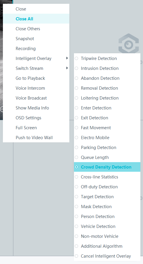
- Right-click a live video pane and choose Intelligent Overlay > Crowd Density Detection from the displayed menu, as shown in Figure 4-245. The real-time intelligent analysis result is superimposed on the video image.
- Viewing alarms
For details about how to view the latest or historical alarms, see Viewing Alarms (on the iClient S100).
- Viewing alarms
Head Counting
Feature Description
Definition
- Cameras count the number of people who are crossing a preset line to head in or out of a detection area and generate an alarm based on the difference between the number of people entering and leaving the area.
- The system receives and processes head counting information and alarms reported by intelligent cameras.
Customer Benefits
- The system automatically detects key information in video, reducing labor costs and improving work efficiency.
- The system supports around-the-clock detection or detection for a specified duration, eliminating issues that may occur due to security personnel's mistakes.
- Users only need to view live video upon an alarm. This allows a user to centrally manage a large number of cameras, reducing labor costs.
Application Scenario
This feature applies to places where entrance and exit events need to be detected, for example, entrances/exits of tourist attractions, campuses, schools, and exhibition halls.
Requirements
NE |
Version Requirement |
License Requirement |
Function |
|---|---|---|---|
HWT-IVS1800-D/HWT-IVS1800-E |
11.1.0 and later versions |
N/A |
Receives head and shoulder information reported by cameras and processes alarms. |
iClient S100 |
V1.6.0 and later versions |
N/A |
Receives and displays head, shoulder, and alarm information from cameras. |
SDC |
Intelligent analysis results superimposed on live video: 9.0.0 and later versions Information reporting through northbound interfaces: 9.0.0 and later versions |
N/A |
Supports crowd flow analysis. |
Application Limitations
Related configurations need to be performed in the camera web system.
Feature Configuration (Based on Cameras)
Scenario Description
Table 4-225 describes the support for this feature in different client scenarios.
Client |
Feature Support |
Reference |
|---|---|---|
LDU |
Supported |
For details, see Procedure (on the LDU). |
Camera web system |
Supported |
Complete the configuration by referring to the product documentation of cameras. |
iClient S100 |
V1.6.0 and later versions |
For details, see Procedure (on the iClient S100). |
Prerequisites
- You have set the parameters listed in Public Configurations.
- You have configured alarm linkage on the iClient S100. For details, see Configuring Alarm Linkage.
Procedure (on the LDU)
To view the configuration guide video, you can click in the upper left corner on the Configuration tab page, and scan the QR code.
- Log in to the LDU as the admin user. ( Logging In to the LDU)
- Click
 in the upper left corner.
 - Choose Intelligent Application > Camera Intelligence > Situation Analysis > Head Counting.
- Configure head counting, as shown in Figure 4-246.
Table 4-226 describes the key parameters, buttons, and icons.
Table 4-226 Parameter/Button/Icon descriptionParameter/Button/Icon
Description
Detection switch
Button for enabling or disabling head counting.
After the switch is toggled on, the head counting function is enabled.
Detection Line
No.
ID of a detection line. Only one detection line can be drawn.
Operation
Column containing the icons for drawing or deleting a detection line on the live video image.
To draw a detection area, select two points on the video image. The system automatically connects the selected points with an arrow specifying the detection line direction to form a semi-closed area.
direction
Customized detection direction. You can click Direction change to change the detection line direction.
Detection Area
No.
ID of a detection area. Only one detection area can be drawn.
Operation
Column containing the icons for drawing or deleting a detection area on the video image.
Configuration
Report people count
Interval at which people count is reported, in seconds.
Alarm Threshold
Alarm threshold of the total number of persons who cross the detection line. If the total number of persons exceeds the alarm threshold, an alarm is generated.
Enable statistics clearance at 00:00
Indicates whether to clear statistics at 00:00. After this function is enabled, the system automatically clears the statistics on the number of persons at 00:00.
Sound And Light Alarm
Audio switch/Twinkle switch
Indicates whether to produce audible alarms (playing audio files) or visual alarms (blinking light) when an alarm is triggered.
Audio Output
Audio file to be played when an alarm is triggered.
- You can directly use this function when an intelligent IR/white-light camera with intercom is used.
- To use this function when a camera other than the intelligent IR/white-light camera with intercom is used, you need to set audio parameters for the camera and connect the camera to an external audio output device.
Frequency
Number of times for playing an audio file when an alarm is triggered.
Twinkle Freq
Frequency at which the light blinks when an alarm is triggered. You can set this parameter to Low frequency, Medium frequency, or High frequency as required.
Currently, the visual alarm (blinking light) function is available only for intelligent IR/white-light cameras with intercom. You need to set light-related parameters.
Twinkle Time(s)
Period in which the light blinks when an alarm is triggered.
- Configure an alert plan, as shown in Figure 4-247.
- Configure an alarm linkage policy, as shown in Figure 4-248.
Table 4-227 describes the key parameters and buttons.
Table 4-227 Parameter/Button descriptionType
Parameter
Description
Common Linkage
Display ID
Indicates whether to display the status icon of the camera that triggers an alarm on the live video viewing page. This function is used to notify users of an alarm generated by the current camera.
Full-Screen Alarm
Indicates whether to display alarms in full screen mode.
After this function is enabled, if a camera triggers an alarm and the live video viewing page is displayed on the LDU, the live video of the camera is played in full screen mode for 5s.
CAUTION:If other alarms are generated when the live video is played in full-screen mode, the full-screen alarm function is not triggered.
Send Email
- Indicates whether to send email notifications. After this function is enabled, the system sends an email to the configured email recipient when a service alarm is generated.
- You can click to customize the alarm email recipient and email body.
The email address for sending service alarms needs to be customized on the OMU portal.
For details about how to set the email address for sending service alarms, see How Do I Configure Connection to the SMTP Server?.
Recording
Channel
Camera to be linked to record video when an alarm is triggered.
Duration(s)
Customized recording duration. The value ranges from 5 to 3600, in seconds. You are advised to set this parameter to a value greater than or equal to 60 (default).
Triggered Snapshot
Channel
Camera to be linked to take snapshots when an alarm is triggered.
NOTE:If both snapshot taking and email sending are configured for alarm linkage, you can obtain both the alarm-triggered snapshots and the snapshots sent in the email.
Stop Recording
Channel
Camera to be linked to stop video recording when an alarm is triggered.
I/O Alarm
Channel ID
Alarm reporting channel.
Duration(s)
Customized alarm linkage duration.
The value ranges from 1 to 3600, in seconds.
NOTE:If the specified alarm linkage duration is different from the I/O alarm output duration configured in How Do I Connect Cables and Configure Alarm Input and Output Ports?, the shorter alarm duration is used.
For example, if the I/O alarm output duration is set to 20s and the alarm linkage duration is set to 30s, the actual alarm output duration is 20s.
Invoke Preset Position
Channel
Camera to be linked. When a service alarm is generated, the linked camera rotates to the specified preset position.
Before enabling preset position linkage, ensure that a preset position has been configured for the camera to be linked. For details about how to configure a preset position, see Feature Configuration.
Device
Name of the camera that is linked to a preset position.
Position
Preset position linked to the camera.

Procedure (on the iClient S100)
- On the iClient S100 home page, choose Maintenance Management > Smart Configuration.
- Click a camera connected to a device and choose .
- Enable crossing-line head counting and set parameters such as detection area parameters, as shown in Figure 4-249.
- Set parameters in the Parameter Settings area. Table 4-228 describes the parameters.
Table 4-228 Parameter description
Parameter
Description
Enable ZeroClear
Indicates whether to clear statistics on the live video viewing page at 00:00 of the next day.
Clear Statistics
Button for clearing the current statistics immediately.
Alarm Detection Interval(s)
Interval at which alarms are checked, in seconds.
Alarm Count
Alarm threshold for the number of persons who cross the detection line.
- Set audible and visual alarm parameters. Table 4-229 describes the parameters.
Table 4-229 Audible and visual alarm parameters
Parameter
Description
Requirement on the Camera
Enable audio alarms
Indicates whether to produce audible alarms (play audio files) when an alarm is triggered.
- You can directly use this function when an intelligent IR/white-light camera with intercom is used.
- To use this function when a camera other than the intelligent IR/white-light camera with intercom is used, you need to set audio parameters for the camera and connect the camera to an external audio output device.
Audio file
Audio file to be played when an alarm is triggered.
To import an audio file to the iClient S100, choose Maintenance Management > Video Device > Device List on the home page, double-click the required camera that is connected to a device, and add an audio file on the Audio Channel tab page.
Playback times
Number of times for playing an audio file when an alarm is triggered.
Enable light flashing alarm
Indicates whether to produce visual alarms (blinking lights) when an alarm is triggered.
Currently, these functions are available when an intelligent IR/white-light camera with intercom is used. You need to set light-related parameters.
White light illuminator
Frequency at which the light blinks when an alarm is triggered. You can set this parameter to Low, Middle, High, or Steady on as required.
Flash duration (s)
Period in which the light blinks when an alarm is triggered.
- Set area parameters. Table 4-230 describes the parameters.
Table 4-230 Area settings
Parameter
Description
Area
Button for drawing the detection area. Only one detection area is supported.
Line
Button for drawing the detection line. Only one detection line is supported.
Delete
Button for deleting a selected detection area or detection line.
Direction
Direction in which a person crosses the detection line.
- A->B: Collects statistics on the number of persons who cross the detection line from A to B.
- B->A: Collects statistics on the number of persons who cross the detection line from B to A.
- Set plan parameters. Table 4-231 describes the parameters.
When the iClient S100 and an HWT-IVS1800 are in different time zones, the time set in the Plan Settings area refers to the time of the HWT-IVS1800.
Table 4-231 Plan settingsParameter/Button
Description
Add
Button for adding an alert plan. A maximum of eight alert plans are supported.
All Delete
Button for deleting all alert plans.
Start Time/End Time
Time segment during which alert is to be deployed.
Date
Date on which an alert plan is to be executed.
- Every day
- Monday to Sunday
Mode
Indicates whether to cyclically execute an alert plan.
- Weekly
- One-off
Operation
To delete the current alert plan, click
in the Operation column.
- Set parameters in the Parameter Settings area. Table 4-228 describes the parameters.
- Click Save.

Feature Verification
You can view crossing-line head counting information using one of the following methods:
- View real-time crossing-line head counting details on the live video viewing page.
- View crossing-line head counting alarms in the alarm center.
- View crossing-line head counting reports on the statistical analysis page.
Verification (Based on the LDU)
- Log in to the LDU as the admin user. ( Logging In to the LDU)
- View alarms on the LDU.
- Viewing real-time alarms
- Right-click on the desktop and choose Live > Alarm List.
- Click and select the type of alarms to be viewed, as shown in Figure 4-250.
- Click an alarm card in the alarm list to view the alarm in full screen mode, as shown in Figure 4-251.
- By default, the alarm-triggered video is 10s long (5s before and 5s after the alarm time).
- If you click , the alarm list on the left stops refreshing the latest alarms. If you click again, the system refreshes all new alarms generated after the alarm refresh stops.
- Viewing historical alarms
- Right-click on the desktop and choose Retrieval.
- Choose Event Retrieval.
- View alarms, as shown in Figure 4-252.
You can click the Browsing Status icon to switch the alarm browsing mode. Alarms in the alarm center can be browsed in card or list mode.
- Viewing real-time alarms
- Viewing statistical results
- Log in to the LDU as the admin user. ( Logging In to the LDU)
- Click
 in the upper left corner.
 - Choose Intelligence > Statistics Analysis > Head Counting.
- View crossing-line head counting reports, as shown in Figure 4-253.
The following table describes the parameters.
Table 4-232 Parameter descriptionParameter
Description
Statistical Method
Statistical method.
- Daily report
- Weekly report
- Monthly report
- Annual report
Date
For a daily report, statistics are collected from 00:00 to 24:00 on the specified day.
For a weekly report, statistics are collected from Monday to Sunday of the specified week.
For a monthly report, statistics are collected from the first day to the last day of the specified month.
For an annual report, statistics are collected from January 1 to December 31 of the specified year.
Search
Searches for statistics.
Export
Exports the current report to a USB flash drive.

Verification (Based on the iClient S100)
- Viewing real-time service details
- On the iClient S100 home page, choose .
- Double-click an online camera in the Devices area or drag the online camera to a live video pane. Then you can view live video from this camera.
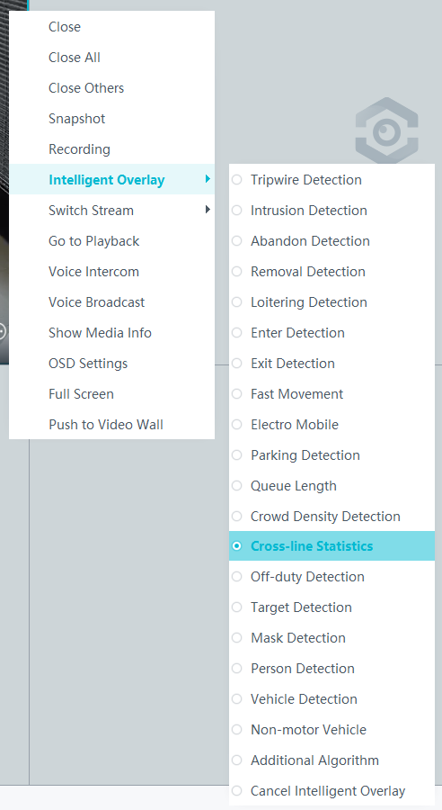
- Right-click a live video pane and choose Intelligent Overlay > Cross-line Statistics, as shown in Figure 4-254. The real-time intelligent analysis result is superimposed on the video image.
- Viewing alarms
For details about how to view the latest or historical alarms, see Viewing Alarms (on the iClient S100).
- Viewing statistical results
- On the iClient S100 home page, choose Intelligent Applications > Statistics > Cross-line Statistics.
- Set filter criteria and view cross-line head counting results, as shown in Figure 4-255.
- Viewing alarms

Heat Map
Feature Description
Definition
Users can superimpose a crowd density heat map on the live or recorded video image to intuitively display the current crowd density distribution.
Customer Benefits
Users can view heap maps to understand the crowd density in a detection area.
Application Scenario
This feature applies to stores where users want to understand which product attracts buyers.
Requirements
NE |
Version Requirement |
License Requirement |
Function |
|---|---|---|---|
HWT-IVS1800-D/HWT-IVS1800-E |
11.1.0 and later versions |
N/A |
Receives and stores heat maps from cameras. |
iClient S100 |
V1.6.0 and later versions |
N/A |
Receives and displays heat maps from cameras. |
SDC |
9.0.0 and later versions |
N/A |
Supports crowd flow analysis. |
Application Limitations
Related configurations need to be performed in the camera web system.
Feature Configuration (Based on Cameras)
Scenario Description
Table 4-233 describes the support for this feature in different client scenarios.
Client |
Feature Support |
Reference |
|---|---|---|
LDU |
Supported |
For details, see Procedure (on the LDU). |
Camera web system |
Supported |
Complete the configuration by referring to the product documentation of cameras. |
iClient S100 |
V1.6.0 and later versions |
For details, see Procedure (on the iClient S100). |
Prerequisites
You have set the parameters listed in Public Configurations.
Procedure (on the LDU)
To view the configuration guide video, you can click in the upper left corner on the Configuration tab page, and scan the QR code.
- Log in to the LDU as the admin user. ( Logging In to the LDU)
- Click
 in the upper left corner.
 - Choose Intelligent Application > Camera Intelligence > Situation Analysis > Heat Map.
- Configure a heat map, as shown in Figure 4-256.
Table 4-234 describes the key parameters.
Table 4-234 Parameter descriptionParameter
Description
Detection switch
Button for enabling or disabling the heat map function. After the switched is toggled on, the heat map function is enabled.
Detection area
Detection area. A maximum of eight detection areas are supported.
To draw a detection area, select polygon vertices on the video image and right-click the image. The system automatically connects the selected vertices to form a closed area.
Send Metadata
Indicates whether to send metadata when the is connected to the upper-level platform.
If this function is enabled, the camera will send metadata such as snapshots and structured data to the upper-level platform. Then the upper-level platform can perform search by criteria based on the metadata sent by the .
- Configure an alert plan, as shown in Figure 4-257.


Procedure (on the iClient S100)
- On the iClient S100 home page, choose Maintenance Management > Smart Configuration.
- Click a camera connected to an HWT-IVS1800 and choose .
- Enable heat map and set parameters such as detection area parameters, as shown in Figure 4-258. Table 4-235 describes the parameters and buttons.
Table 4-235 Parameter/Button description
Parameter/Button
Description
Enable HeatMap
Indicates whether to enable the heat map function for a camera.
Send Metadata
Indicates whether to send metadata. After this function is enabled, the camera sends the heat map result to the iClient S100.
Add Area
Button for drawing the detection area. A maximum of eight detection area is supported.
Delete
Button for deleting a selected detection area.

Feature Verification
You can view heat map reports on the statistical analysis page.
Checking Statistical Results (Based on the LDU)
- Log in to the LDU as the admin user. ( Logging In to the LDU)
- Click
 in the upper left corner.
 - Choose Intelligent Application > Statistics Analysis > Heat Map Statistics.
- View heat map reports, as shown in Figure 4-259.
Table 4-236 describes the parameters and buttons.
Table 4-236 Parameter/Button descriptionParameter/Button
Description
Statistical Method
Statistical method.
- Daily report
- Weekly report
- Monthly report
- Annual report
Date
For a daily report, statistics are collected from 00:00 to 24:00 on the specified day.
For a weekly report, statistics are collected from Monday to Sunday of the specified week.
For a monthly report, statistics are collected from the first day to the last day of the specified month.
For an annual report, statistics are collected from January 1 to December 31 of the specified year.
Search
Searches for statistics.

Checking Statistical Results (Based on the iClient S100)
- On the iClient S100 home page, choose Intelligent Applications > Statistics > Heat Map.
- Set filter criteria and view heat map statistics.
- View spatial heat map, as shown in Figure 4-260.
- View temporal heat map, as shown in Figure 4-261.

